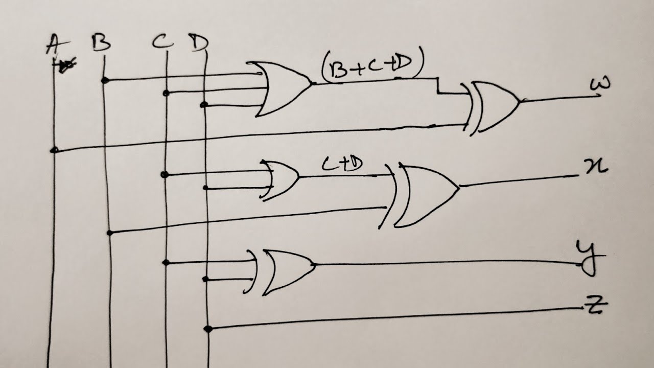
[diagram] 2 s complement logic diagram 2's complement in digital electronics [diagram] 2 s complement logic diagram
Figure 6 from Design and Implementation of High Performance Two’s
Two's complement circuit Two’s complement 2's complement circuit diagram
2's complement circuit. compared to a conventional adder 2's complement
Bit subtractor complement circuit adder solved show transcribed problem text been hasFigure 6 from design and implementation of high performance two’s The second circuit performs addition. first, we'll study a circuit2's complement circuit diagram.
Verilog: addition and subtraction using verilog's 2's complement2 s complement circuit diagram 2's complement circuit2's complement in digital electronics.

4.10 design a four-bit combinational circuit 2's complementer. (the
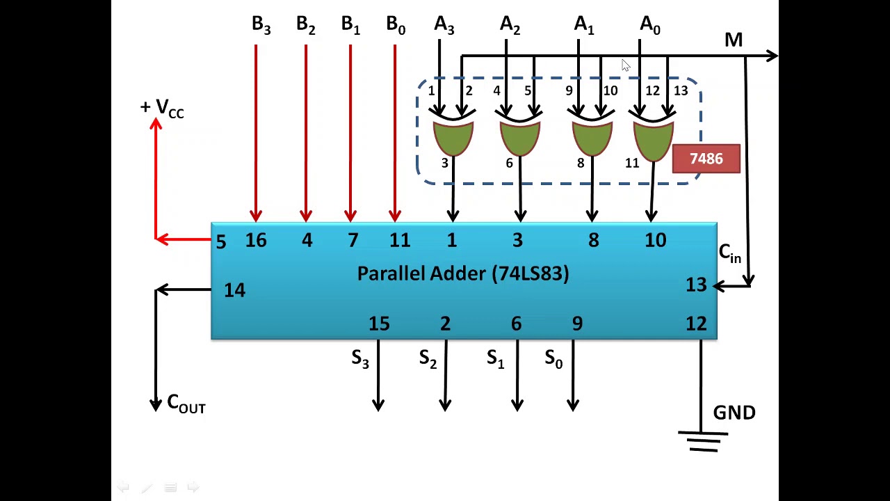
Solved for the 4-bit 2's complement adder/subtractor circuitComplement 2s positive representation Modified two's complement circuit for 32-bit input.Boolean algebra.
Logic not function2 s complement circuit diagram Complement logic gates using only two circuit twos computer science inputs stack below exchangeIn this problem, you will design a 4-bit 2's complement sub tractor.

2's complement circuit. compared to a conventional adder 2's complement
2s complement combinational circuit2's complement circuit diagram Complement twos 2s javatpoint msb2 s complement circuit diagram.
Complement circuit twoComplement circuit 2's complement circuit diagramComplement two circuit serial ppt powerpoint presentation logic.
Virtual labs
2's complement circuit diagram2′s complement 2's complement circuitComplement 2s logic bit binary javatpoint.
2 s complement circuit diagram2's complement circuit diagram Complement logic adder gates implement numbers microcontroller 1s coded4 bit full adder circuit diagram.


2's Complement circuit. Compared to a conventional adder 2's complement
2's Complement Circuit

Logic NOT Function - Electronics-Lab.com

2's Complement Circuit Diagram

2′s Complement

2's Complement Circuit Diagram

Virtual Labs
![[DIAGRAM] 2 S Complement Logic Diagram - MYDIAGRAM.ONLINE](https://i2.wp.com/www.researchgate.net/profile/Praveena_Murugesan/publication/269984827/figure/download/fig8/AS:668575895396369@1536412323652/Twos-complement-circuit.png)
[DIAGRAM] 2 S Complement Logic Diagram - MYDIAGRAM.ONLINE